FirewallBuilder |
|
|
Search Users Guide

In this example, we work with two Linux machines running heartbeat for failover that form a High Availability (HA) firewall pair, and another machine behind them that will use this pair as a firewall. The set up is shown in figure Figure 14.137. Machines linux-test-1 and linux-test-2 are the firewalls and linux-test-3 is a workstation behind them. All testing is done on an isolated network using private IP addresses, subnet "outside" the firewalls is 10.3.14.0/255.255.255.0 and subnet "behind" the firewalls is 10.1.1.0/255.255.255.0. In fact, this network was located behind a router and another firewall that provided connection to the Inetrnet. In real configurations subnet that is 10.3.14.0 here will probably use publicly routable IP addresses.

Note
IPv6 addresses are not used in this recipe. Some interface objects in the screenshots have IPv6 addresses because firewall objects were "discovered" using SNMP which finds IPv6 addresses. You can disregard these addresses while working with examples in this chapter.
As shown in Figure 14.137, machines linux-test-1 and linux-test-2 run heartbeat daemon (Linux-HA home page) to create virtual IP address on both subnets. The heartbeat adds virtual IP address to the same interface eth0 or eth1. One of the daemons becomes master and takes ownership of the virtual address by adding it to the interface with the label "eth0:0" or "eth1:0".
Note
Section 8.1 explains that this "eth0:0" is not an interface and should not be used as the name of the interface object in Firewall Builder configuration. See Section 8.1 for a more detailed explanation.
The heartbeat sends a UDP datagram to the multicast address 225.0.0.1 every second or so to declare that it is up and running and owns the address. If the machine it is running on shuts down for any reason, this stream of packets from the master stops and after a predetermined timeout, the second machine becomes master and assumes the virtual IP address. The heartbeat actually is more complex than that: it can be configured to monitor certain resources on the machine and give up the address if some conditions are met. In that case, two daemons negotiate transfer of the address from one machine to another and the second machine becomes active. These aspects of heartbeat configuration are outside the scope of this manual and we will not go into more details about it. See heartbeat documentation on Linux-HA home page or heartbeat manual for that.
Unlike VRRPd, heartbeat does not replace the MAC address of the active machine with a virtual one: it uses gratutious ARP to announce the changing of the MAC address. This does not change anything in the Firewall Builder configuration for the cluster.
Assuming you have followed installation instructions for the heartbeat and have correct package on the machine, you can build simple configuration for it by creating just three files:
ha.cf, the main configuration file
haresources, resource configuration file
authkeys, authentication information
Here is the configuration for the test setup I am using:
Figure 14.138. Heartbeat configuration files
# cat ha.cf:

mcast eth0 225.0.0.1 694 1 0
mcast eth1 225.0.0.1 694 1 0
auto_failback on
node linux-test-1
node linux-test-2


# cat haresources

linux-test-1 IPaddr::10.3.14.150/24/eth0/10.3.14.255
linux-test-1 IPaddr::10.1.1.254/24/eth1/10.1.1.255


# cat authkeys

auth 3
3 md5 hb-auth-key
This tells the heartbeat to run two sessions, on interfaces eth0 and eth1, using multicast with default group address 225.0.0.1 and udp port 694. There are two nodes, "linux-test-1" and "linux-test-2". File haresources defines virtual IP addresses on both subnets and file authkeys sets up MD5 authentication with a simple shared key. A nice aspect of the heartbeat configuration is that all three files are identical on both machines in the cluster. File authkeys should have permissions "0600", other files can have permissions "0644":
root@linux-test-1:/etc/ha.d# ls -la authkeys  haresources ha.cf
-rw------- 1 root root   648 2010-02-03 09:17 authkeys
-rw-r--r-- 1 root root 10610 2010-02-03 09:28 ha.cf
-rw-r--r-- 1 root root   106 2010-02-04 10:21 haresources
Now we can start the heartbeat on both machines using "/etc/init.d/heartbeat start" command (on Ubuntu). If everything is done correctly, the heartbeat daemons should come up and after a while one of them becomes active. Which one is determined by the node name that is the first word in each line of the haresources file. Daemons log their progress, as well as warnings and errors in the /var/log/messages file. When the active daemon takes over the virtual IP address, it is added to the interface and look like this (virtual addresses are highlited in red):
root@linux-test-1:~# ip -4 addr ls
1: lo: <LOOPBACK,UP,LOWER_UP> mtu 16436 qdisc noqueue state UNKNOWN
    inet 127.0.0.1/8 scope host lo
2: eth0: <BROADCAST,MULTICAST,UP,LOWER_UP> mtu 1500 qdisc pfifo_fast state UNKNOWN qlen 1000
    inet 10.3.14.108/24 brd 10.3.14.255 scope global eth0
    inet 10.3.14.150/24 brd 10.3.14.255 scope global secondary eth0:0
3: eth1: <BROADCAST,MULTICAST,UP,LOWER_UP> mtu 1500 qdisc pfifo_fast state UNKNOWN qlen 1000
    inet 10.1.1.1/24 brd 10.1.1.255 scope global eth1
    inet 10.1.1.254/24 brd 10.1.1.255 scope global secondary eth1:0

root@linux-test-2:~# ip -4 addr ls
1: lo: <LOOPBACK,UP,LOWER_UP> mtu 16436 qdisc noqueue state UNKNOWN
    inet 127.0.0.1/8 scope host lo
2: eth0: <BROADCAST,MULTICAST,UP,LOWER_UP> mtu 1500 qdisc pfifo_fast state UNKNOWN qlen 1000
    inet 10.3.14.109/24 brd 10.3.14.255 scope global eth0
3: eth1: <BROADCAST,MULTICAST,UP,LOWER_UP> mtu 1500 qdisc pfifo_fast state UNKNOWN qlen 1000
    inet 10.1.1.2/24 brd 10.1.1.255 scope global eth1
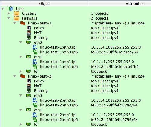
Now we can create objects in Firewall Builder to represent this cluster. We start with two firewall objects configured with ip addresses but no policy or NAT rules. Interfaces and their addresses and netmasks are shown on Figure 14.139:
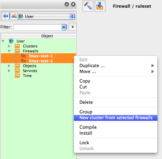
Now create the new cluster. First, select firewalls "linux-test-1" and "linux-test-2" in the tree, then click right mouse button to open context menu and use item "New cluster from selected firewalls" as shown on Figure 14.140.
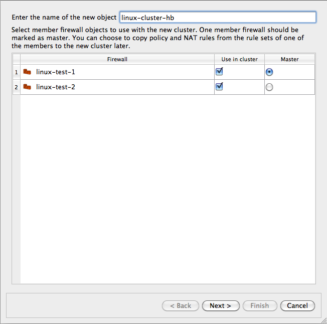
This method opens up the wizard that creates a new cluster object with the list of the firewalls that shows two firewalls that were selected in the tree:
After you click "Next", you arrive on the next page where you establish correspondence between cluster interfaces and interfaces of the member firewalls. The program finds interfaces of the members with the same name that can be used for a cluster and preconfigures cluster interfaces using this information. In our case, it created cluster interfaces "eth0", "eth1" and "lo" and mapped them to the inetrfaces with the same name in both members. See Figure 14.142:
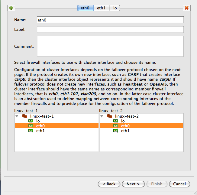
This example is straightforward because there is a direct correspondence between them. In more complex cases, member firewalls may have different number of interfaces, only some of which should be used for the cluster configuration. Or failover protocol used for the cluster may create its own interfaces, such as CARP on OpenBSD. In that case, the name of the interface that is configured at the top of the wizard page would be "carp0" and we would map it to interfaces of the members, say "en0" on both, using controls at the bottom of the wizard page. However, the heartbeat does not create the new interface so the cluster interface objects must have the same name as corresponding member interfaces; in our case "eth0", "eth1" and "lo". You can create new cluster interfaces or delete existing ones on this page using the "+" and "x" buttons. See Section 8.1 for more information on the cluster interfaces in Firewall Builder.
We assign IP addresses and choose failover protocols for the cluster interfaces on the next page of the wizard Figure 14.143:
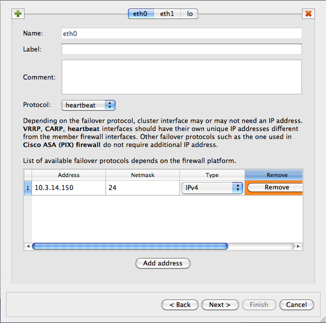
Most protocols require an IP address, which you can add by clicking "Add address" button. The only exception at this time is Cisco PIX, where HA pair uses IP addresses of the master instead of using special virtual addresses. In that case the part of the wizard page where you configure IP addresses will be disabled.
Choose the failover protocol using drop-down list. Among other "real" protocols list includes item "None". Use this item if you do not want fwbuilder to add automatic policy rules to the generated configuration and plan to do this yourself. Also use this "protocol" to configure cluster loopback interface. In any case cluster interfaces must be configured with corresponding interfaces of the member firewalls to establish the mapping.
Note
The address and netmask pair of the cluster interface must be configured exactly the same as done by the cluster software. In the case of the heartbeat, the netmask is /24. See the output of "ip addr show" command above where it is visible that the address added by heartbeat comes with netmask /24. The netmask is defined in the "haresources" file. We use the same netmask in the address configuration in cluster interfaces eth0 and eth1. See Section 14.4.2.4 for the explanation of why this netmask is important.
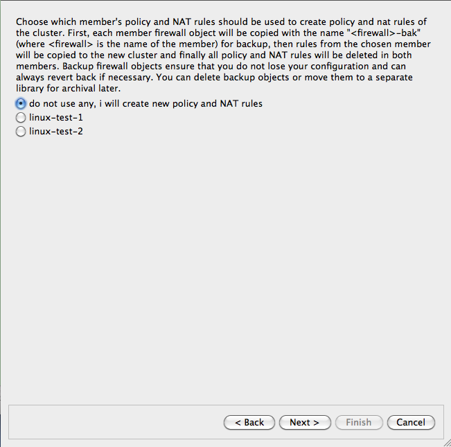
Final page of the wizard Figure 14.144 allows you to choose to copy policy and NAT rules from one of the members to the new cluster object. This can be useful if you used to manage a cluster with fwbuilder by maitaining two firewall objects manually or with the aid of external scripts. If you decide to use this option, the Firewall Builder GUI copies policy and NAT rules from the member you choose to the new cluster object, then creates backup copies of both member firewall objects with the name with suffix "-bak" and deletes all policy and NAT rules in the rule sets of the member firewall objects it uses for the cluster. This way, you can always return to your old setup using these backup objects and at the same time, new cluster configuration has all the rules in the cluster object.
Note
This is important because if a member firewall object has a policy or NAT rule set with the same name as the one in the cluster, then Firewall Builder will use rules from the rule set of the member, thus overriding all the rules in the cluster's rule set with the same name. This allows you to create complex configurations where majority of the rules are defined and maintained in the cluster object, but a few rules can be created separately in the members to complement rules of the cluster.
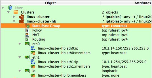
The following screenshot Figure 14.145 demonstrates a newly created cluster object.
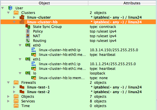
Each cluster interface has an additional child object (located underneath it in the tree) with the name linux-test-1:eth0:members and linux-test-1:eth1:members. These objects are failover groups, this is where the failover protocol and mapping between the cluster and member interfaces is configured. The screenshot Figure 14.146 highlights failover group that belongs to interface eth0:
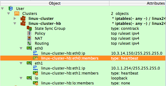
The failover group is configured with the name, protocol, and interfaces of the member firewalls that correspond to the cluster interface this failover group belongs to. Failover group object selected on Figure 14.146 looks like this:
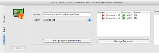
The ailover group for the interface eth1 should look the same, except for using interfaces eth1 of the member firewalls. Use button Manage Members to open a dialog that lets you add and remove member firewall interfaces in the failover group.
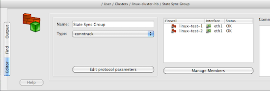
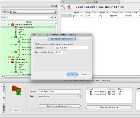
Another new type of object that appears in the clusters is the state synchronization group Figure 14.148. This group object defines state synchronization protocol used for the cluster and interfaces of the member firewalls where this protocol runs. In the case of Linux firewalls only conntrack protocol is available.
Note
The purpose of this new object is to provide all necessary configuration parameters to let Firewall Builder generate policy rules to permit packets of this protocol. In some other cases, such as with PF on OpenBSD where state synchronization is done via pfsync interface, Firewall Builder can generate actual configuration for the protocol itself. However at this time Firewall Builder does not generate configuration or command line for the conntrackd daemon.
Just as for failover group objects, a state synchronization group object is configured with the name, protocol, and member interfaces:
If you do not use conntrackd in your cluster set-up and do not need iptables rules to permit its packets in the generated script, then just do not configure state synchronization group object with interfaces of the member firewalls. Such empty state synchronization group object will look like this when opened in the editor:
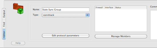
You can edit parameters of the state synchronization protocol, such as the IP address of the multicast group it uses and port number if you click the Edit protocol parameters button:
Firewall Builder uses this information to generate policy rules to permit conntrack packets. See examples of the output generated by the policy compiler below.
Note
There is very little difference between building a cluster using VRRPd or heartbeat in Firewall Builder. To switch from one protocol to the other you would need to do the following:
Open each failover group object in the editor and change protocol
VRRPd uses netmask /32 for the virtual IP addresses, so if your heartbeat setup uses /24, then you need to change these too.
This is it. If your heartbeat setup uses /32 netmask, then all you need to do is switch the protocol in the failover groups.
Note
Examples in this recipe illustrate another useful feature of cluster configurations in Firewall Builder: cluster object "linux-cluster-hb" used in this recipe and cluster object "linux-cluster" from the previous one (Section 14.4.2) use the same firewall objects as member firewalls but generate configurations for clusters based on different failover protocols. The same member firewall object may be used with several cluster objects to test different configurations or for migration.
Now we can move on to building cluster policy and NAT rules. In the examples below I am using a Firewall Builder feature that lets you quickly compile a single rule and see the result in the bottom panel of the GUI immediately. To do this, right-click anywhere in the rule to open context menu and use the item "Compile" or highlight the rule and hit keyboard key "X". Figure 14.152
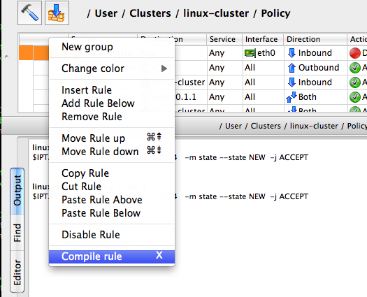
Figure 14.153 shows a minimal policy rule set for the cluster that demonstrates general principles used by Firewall Builder to generate configurations for the member firewalls.
Figure 14.153. Simple Policy for the Cluster, Also Showing Generated iptables Commands for the Anti-Spoofing Rule

Let's inspect the policy rules shown in Figure 14.153. All rules are built with the global option "Assume firewall is part of any" turned off in both linux-test-1 and linux-test-2 firewalls.
Rule 0: anti-spoofing rule. When we build anti-spoofing rule for a standalone firewall, we put firewall object in "Source", its external interface in "Interface" and make direction "Inbound". When we do this for a cluster, we put cluster object in "Source" instead of the member firewall object. The interface object in "Interface" element of this rule is the one that belongs to the cluster rather than its members. All other aspects of the rule are the same. Firewall Builder generates iptables commands for this rule using ip addresses of the cluster (10.3.14.150 and 10.1.1.254 in our example) and addresses of the member firewall it compiles for, in this case 10.3.14.108 and 10.1.1.1 for linux-test-1 and 10.3.14.109 and 10.1.1.2 for linux-test-2. This is clearly visible in the generated output shown in Figure 14.153. In other words, policy compiler processes rules twice, first compiling for the first member firewall and then for the second one. On each pass, cluster object represents corresponding member, plus virtual addresses configured in the cluster's interfaces.
-
Rules 1 and 2: heartbeat can be configured to use either multicast or unicast addresses. See below for the example of configuration with unicast addresses, but by default it is assumed to use multicast. Rules 1 and 2 permit IGMP packets that the system needs to be able to join multicast group. Rules 1 and 2 permit packets sent to the standard multicast address registered for IGMP in both directions (in and out). These rules use standard IPv4 address object "IGMP" that is available in the Standard objects library. The rules could be even more restrictive and also match IP service object "IGMP", also available in the Standard objects library. Since this service object matches protocol number 2 and IP option "router-alert". Unfortunately only the very latest Linux distributions ship the iptables module ipv4options that is needed to match IP options so I did not put the service object in the rule. Here is how the generated iptables script look like when "Service" field on the rules 1 and 2 is "any"
linux-test-1 / Policy / rule 1
$IPTABLES -A OUTPUT -d 224.0.0.22 -m state --state NEW -j ACCEPT

linux-test-2 / Policy / rule 1
$IPTABLES -A OUTPUT -d 224.0.0.22 -m state --state NEW -j ACCEPT
linux-test-1 / Policy / rule 2 $IPTABLES -A INPUT -s 224.0.0.22 -m state --state NEW -j ACCEPT linux-test-2 / Policy / rule 2 $IPTABLES -A INPUT -s 224.0.0.22 -m state --state NEW -j ACCEPTIf I put standard IP service object "IGMP" in the "Service" field of rules 1 and 2, I get the following iptables commands for the rule 1:
linux-test-1 / Policy / rule 1 $IPTABLES -A OUTPUT -p 2 -d 224.0.0.22 -m ipv4options --ra -m state --state NEW -j ACCEPT linux-test-2 / Policy / rule 1 $IPTABLES -A OUTPUT -p 2 -d 224.0.0.22 -m ipv4options --ra -m state --state NEW -j ACCEPT -
The rest of the rules are fairly usual and serve to illustrate that building a policy for the cluster is no different than building the policy for a regular standalone firewall. Rules 3 and 4 permit access from the firewall to internal network and the other way around. The generated iptables commands use INPUT and OUTPUT chains and look like this:
linux-test-1 / Policy / rule 3
$IPTABLES -A OUTPUT -d 10.1.1.0/24 -m state --state NEW -j ACCEPT

linux-test-2 / Policy / rule 3
$IPTABLES -A OUTPUT -d 10.1.1.0/24 -m state --state NEW -j ACCEPT
linux-test-1 / Policy / rule 4 $IPTABLES -A INPUT -s 10.1.1.0/24 -m state --state NEW -j ACCEPT linux-test-2 / Policy / rule 4 $IPTABLES -A INPUT -s 10.1.1.0/24 -m state --state NEW -j ACCEPT Rule 5 permits outbound access from the internal net to the Internet and uses chain FORWARD. The generated iptables code for this rule is no different from that produced for a regular standalone firewall.
Note that we don't need to add explicit rule to permit heartbeat and conntrackd packets to the policy. This is because fwbuilder adds these rules automatically. Here is how they look like in the generated iptables script for the linux-test-1 firewall:
# ================ Table 'filter', rule set Policy
#
# Rule -6 heartbeat (automatic)
#
$IPTABLES -A OUTPUT -o eth1 -p udp -m udp -d 224.0.10.100 --dport 694 -j ACCEPT
#
# Rule -5 heartbeat (automatic)
#
$IPTABLES -A INPUT -i eth1 -p udp -m udp -d 224.0.10.100 --dport 694 -j ACCEPT
#
# Rule -4 heartbeat (automatic)
#
$IPTABLES -A OUTPUT -o eth0 -p udp -m udp -d 224.0.10.100 --dport 694 -j ACCEPT
#
# Rule -3 heartbeat (automatic)
#
$IPTABLES -A INPUT -i eth0 -p udp -m udp -d 224.0.10.100 --dport 694 -j ACCEPT
#
# Rule -2 CONNTRACK (automatic)
#
$IPTABLES -A OUTPUT -o eth1 -p udp -m udp -d 225.0.0.50 --dport 3780 -j ACCEPT
#
# Rule -1 CONNTRACK (automatic)
#
$IPTABLES -A INPUT -i eth1 -p udp -m udp -d 225.0.0.50 --dport 3780 -j ACCEPT
The rules for conntrack are associated with ineterface eth1 because the state synchronization group is configured with interfaces eth1 of the member firewalls (Figure 14.149).
Failover protocol heartbeat and state synchronization protocol conntrack can work using either multicast or unicast addresses. Configuration described in this recipe so far used multicast addresses for both. To switch to unicast, you need to change configuration of heartbeat in the ha.cnf file to use unicast. Here is how it looks like for the machine linux-test-1:
# cat ha.cnf
ucast eth0 10.3.14.109
ucast eth1 10.1.1.2
Before, when heartbeat was configured to use multicast, the ha.cnf file was identical on both cluster member firewalls. Now that each machine is configured with IP address of the other machine in the cluster, ha.cnf files are different.
Apparently conntrackd can also work using unicast addresses however I can not provide example of its configuration.
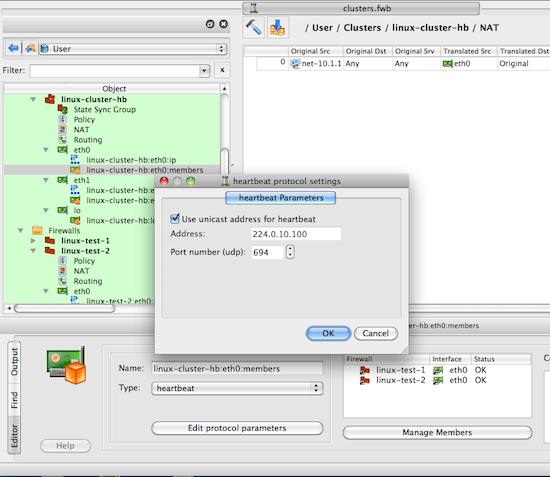
To build iptables rules for heartbeat and conntrack working with unicast addresses, open failover group objects associated with cluster interfaces as shown in Figure 14.146 and Figure 14.147, click "Edit protocol parameters" button and turn on checkbox "Use unicast address":
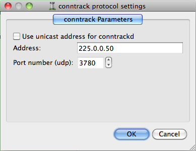
To switch to unicast for conntrackd, open the state synchronization group object in the editor and click the "Edit protocol parameters" button, then check the "Use unicast address" checkbox:
Note
When you switch to unicast, the "Address" input field in the heartbeat and conntrack protocol parameters dialogs becomes disabled.
Switching to unicast makes Firewall Builder generate iptables commands that match IP address of the peer firewall for the corresponding interface pair. Here is the script generated for the machine linux-test-1:
# Rule -4 heartbeat (automatic)
#
$IPTABLES -A OUTPUT -o eth0 -p udp -m udp -d 10.3.14.109 --dport 694 -j ACCEPT
#
# Rule -3 heartbeat (automatic)
#
$IPTABLES -A INPUT -i eth0 -p udp -m udp -s 10.3.14.109 --dport 694 -j ACCEPT
#
# Rule -2 CONNTRACK (automatic)
#
$IPTABLES -A OUTPUT -o eth1 -p udp -m udp -d 10.1.1.2 --dport 3780 -j ACCEPT
#
# Rule -1 CONNTRACK (automatic)
#
$IPTABLES -A INPUT -i eth1 -p udp -m udp -s 10.1.1.2 --dport 3780 -j ACCEPT
Now let's look at the NAT rule built for this cluster Figure 14.156
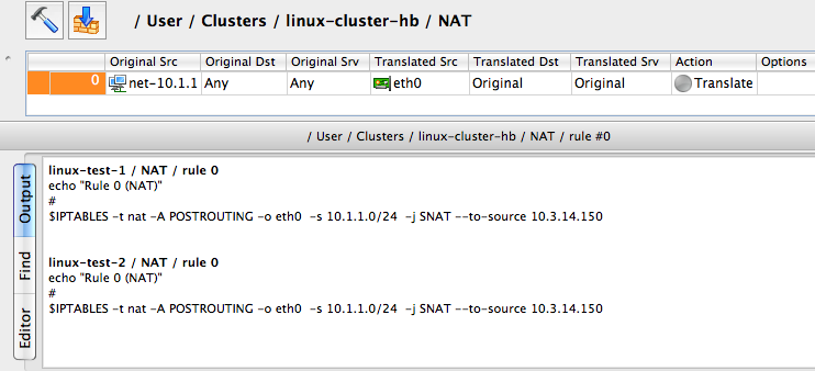
The interface eth0 used in the "Translated Source" element of this rule is the one that belongs to the cluster, not member firewalls. The generated iptables commands use the cluster interface that belongs to this interface for the translation. Otherwise, this is a very straightforward SNAT rule.
In order to ensure the environment in which generated iptables rules will work really matches assumptions under which these rules were generated, Firewall Builder can manage the IP addresses of the interfaces of the firewall machine. This feature is optional and is controlled by the checkbox "Configure interfaces of the firewall machine" in the "Script" tab of the firewall object "advanced settings" dialog, Figure 14.157:
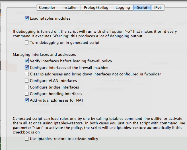
The reason for this is that if the program generates rules
assuming certain addresses belong to the firewall, but in fact
they do not, packets will go into chains different from those
used in the generated iptables commands and the behavior of the
firewall will be wrong.
The code that manages the addresses of interfaces should be able to find and ignore addresses added by the failover daemons such as VRRPd, heartbeat, or keepalived. The program does this by looking at the IP addresses of the cluster interfaces. It is important, therefore, to configure these addresses exactly as they are done by the failover daemons, including both the address and netmask. The heartbeat configuration used in the recipe Figure 14.138 configures virtual IP address with netmask /24. The addresses of the cluster interfaces must be configured in exactly the same way; otherwise, the generated script will kill them when it activates firewall policy. This is shown in Figure 14.143
Copyright © 2000-2012 NetCitadel, Inc. All rights reserved.
Using free CSS Templates.